9 Aralık 2010 Perşembe
60 saniye LED ekran zamanlayıcı
Bu devre bir ibreli kronometrenin LED ler ile simüle edilmiş şeklidir. 1-60sn kadar sayar ve zamanı LED'ler ile gösterir. İşlevselliğinin yanısıra LED'li ışık şovlarına ilgi duyanlar için de tavsiye edilebilecek bir uygulamadır.
AÇIKLAMALAR:
İki adet 4017 ve iki adet 4069 kullanılarak düzenlenmiş bu devre 60sn lik bir ibreli mekanik kronometrenin LED'ler ile düzenlenmiş benzeridir. Devreye enerji verildiği andan itibaren sıra ile 1 ... 60 LED yanar. Herbir LED'in yanma süreri 1sn dir. Dolayısı ile 60 sn (1dk) bir kronometre gerçekleştirilmiş olur.
Devrenin çalışması. U1 birler basamağı sayıcısıdır ve 10'a kadar sayar. U2 onlar basamağı sayıcısıdır ve 6'ya kadar sayar. U4 invertör entegresi ile hangi onlar basamağında hangi led dizisinin devrede olacağını belirleyen anahtarlama işlemini yapar. U3 entegresi devrenin çalışma frekansını belirleyen osilatör devresidir. Devre 1 den 60'a kadar sayan basit bir sayıcıdır.
Devreye enerji verdikten sonra, U3 (4069) entegresinin A ve B kapıları ile kurulmuş osilatörün frekansını 1sn (1Hz) olacak şekilde ayarlayınız. Aşağıda devre şemasında devrenin çalışması görülmektedir. Bu çizimde 0 dan 60'a kadar olan tüm adımlar gösterilmemiştir.
Çalışma gerilimi : 5V
Çalışma akımı : 50mA
DEVRENİN AÇIK ŞEMASI :
İzleyiciler
TIMING CALCULATORS FOR THE LM555
LED DİRENÇ HESAPLAMA
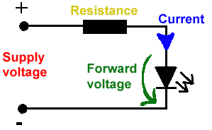
All LEDs require current limiting, without a current limiting mechanism the LED will usually burn out in under a second. Adding a simple resistor is the easiest way to limit the current. Use the calculator below to find out the value of resistor you require.
For example if you are wanting to power one of our_blank">red LEDs in an automotive application you would see that the typical forward voltage is 2.0 Volts and the maximum continuous forward current is 30mA. Therefore you would enter 14.5, 2.0 and 30 into the Single LED calculation box. After calculating you get 470ohm 1 watt as the result. Here is a that allows you to enter a resistor value and generate the corresponding color code.
Note: For automotive applications use the actual system voltage, not 12 Volts. Most 12 Volt system actually operate at around 14.5 Volts.
Lm317 uygulama devreleri ve detayli bilgiye Buradan ulasabilirsiniz |
LM555 - ASTABLE OSCILLATOR CALCULATOR
NOTE: The leakage currents of electrolytic capacitors will affect the actual output results of the timers. To compensate for leakage it is often better to use a higher value capacitor and lower value resistances in the timer circuits.
LM555 Astable Oscillator Circuit Diagram
The next calculator can find the capacitance needed for a particular output frequency if the values of R1 and R2 are known.
Value Of R1 Ohms | Value Of R2 Ohms |
Frequency Desired Hertz |
| |
|
Hiç yorum yok:
Yorum Gönder