9 Aralık 2010 Perşembe

27kHz civarında frekans üreten devre

27kHz civarında frekans üreten devre
"Bu devre insan kulağının duyamadığı bölgede ultrasonic ses sinyalleri üretir. İnsanların duyamadığı bu sesleri bazı hayvanlar duyabilir.Köpekler 27kHz civarındaki sesleri duyabilir. Yeterince güclü bir tonla köpekler rahatsız edilebilir.

Devrenin teorisi oldukça basittir. U1a ve U1b kapıları ile kurulan osilatörün ürettiği frekans değerini C1 ve RV3+R2 elemanları belirler. Şemadaki RV3 ayarlı direnci ile istenen çıkış frekansı ayarlanır. Bu ayarı yapmak için size bir frekans metre gerekecektir.

U1c ve U1d Tam köprü tipi sürücü devresine ait transistörleri sürme görevini üstlenmişlerdir. Bu sayede osilatör frekansı çıkış yüklerinden etkilenmez.

Ultrasonic ses üreteci olarak mutlaka üretilecek frekans değerine uygun transdüserler kullanmak gerekir. Bunlar özel malzemelerdir. Çoğunlukla da temn etmek zordur. Pratik olarak (tavsiye niteliğinde) kaliteli bir piezo hoparlörde sonuç verebilir.(Etiketindeki çalışma frekanslarına bakmalısınız). En azından temini kolaydır. Kabacası devrenin başarısı kullanacağınız ultrasonic piezo hoparlör ile doğrudan alakalıdır.

Ultrasonic olsun, normal frekanslarda çalışan bir piezo hoparlör olsun, bunları normal (manyetik) hoparlörler gibi düşünmemek gerekir. Piezolar ancak üzerindeki gerilimin yönü değiştirilirse (AC) ses üretebilirler. Bu amaçla, DC motor sürücülerinde sıkça kullanılan Tam köprü (H-BRIDGE) sürücü devresi ile çalıştırılmıştır.

Aynı devre başka frekanslar araştırılarak böcek kovucu, sivrisinek kovucu v.b. uygulamalarda değerlendirilebilir.

Devreyi 9Voltluk pil ile çalıştırabilirsiniz.

Yapmadan önce 4093 entegresine ait bilgileri araştırmayı unutmayın.

Hiç yorum yok:

Yorum Gönder

İzleyiciler

LED DİRENÇ HESAPLAMA

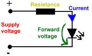
All LEDs require current limiting, without a current limiting mechanism the LED will usually burn out in under a second. Adding a simple resistor is the easiest way to limit the current. Use the calculator below to find out the value of resistor you require.

For example if you are wanting to power one of our_blank">red LEDs in an automotive application you would see that the typical forward voltage is 2.0 Volts and the maximum continuous forward current is 30mA. Therefore you would enter 14.5, 2.0 and 30 into the Single LED calculation box. After calculating you get 470ohm 1 watt as the result. Here is a that allows you to enter a resistor value and generate the corresponding color code.

Note: For automotive applications use the actual system voltage, not 12 Volts. Most 12 Volt system actually operate at around 14.5 Volts.

Supply Voltage
VOLTS
Voltage Drop Across LED
VOLTS
Desired LED Current
MILLIAMPS


Calculated Limiting Resistor
OHMS
Nearest higher rated 10% resistor

Calculated Resistor Wattage
WATTS
Safe pick is a resistor with
power rating of (common values are .25W, .5W, and 1W)
WATTS

LEDs in series

Several leds in series with one resistor
Supply Voltage
VOLTS
Voltage Drop Across LED
VOLTS
Desired LED Current
MILLIAMPS
How many LEDs connected


Calculated Limiting Resistor
OHMS
Nearest higher rated 10% resistor

Calculated Resistor Wattage
WATTS
Safe pick is a resistor with
power rating of (common values are .25W, .5W, and 1W)
WATTS
LM317 UYGULAMA DEVRELERİ HESAPLAMASI


Çıkış Voltajı
R1 resistor

R2 resistor

R1 resistor
R2 resistor

Çıkış Voltajı


Lm317 uygulama devreleri ve detayli bilgiye Buradan ulasabilirsiniz

LM555 - ASTABLE OSCILLATOR CALCULATOR

LM555 - ASTABLE OSCILLATOR CALCULATOR
Value Of R1 Ohms Value Of R2 Ohms
Value Of C1 Microfarads
Output Time HIGH SECONDS Output Time LOW SECONDS Output Period HIGH + LOW SECONDS Output Frequency HERTZ Output Duty Cycle PERCENT
Resistor values are in Ohms (1K = 1000) - Capacitor values are in Microfarads (1uF = 1)

NOTE: The leakage currents of electrolytic capacitors will affect the actual output results of the timers. To compensate for leakage it is often better to use a higher value capacitor and lower value resistances in the timer circuits.

LM555 Astable Oscillator Circuit Diagram


LM555 - ASTABLE CAPACITOR CALCULATOR

The next calculator can find the capacitance needed for a particular output frequency if the values of R1 and R2 are known.

Value Of R1 Ohms Value Of R2 Ohms
Frequency Desired Hertz
Capacitance uF
s

VOLT AMPER OHM ve WATT HESAPLAMA

Current:
kA (kiloamps) A (amps) mA (milliamps) µA (microamps)
Voltage:
kV (kilovolts) V (volts) mV (millivolts) µV (microvolts)