9 Aralık 2010 Perşembe

12 Volt 100 Watt 220 Volt AC konvertör


12Volt 'dan 100Watt gücünde 22V AC konvertör devresi. 12 Volt ile şebeke gerilimi ile çalışan cihazları çalıştırma için kullanılır.


AÇIKLAMALAR

Devre otomobil içerisinde 220V AC ile çalışan radyo, müzik seti, küçük televizyon, tıraş makinesi v.b. cihazları çalıştırmak maksadıyla tasarlanmıştır. 220V çıkış gerilimde 100W lık çıkış gücü verebilen devre ile 100W'a kadar olan cihazlar çalıştırılabilir.

Devre, 40Hz..60Hz arası kare dalga üreten transistörlü multivibratör, sürücü katı, güç katı ve çıkış transformatörü olmak üzere üç kısımdan oluşmuştur. Multivibratörün ürettiği iki fazlı sinyal BD139 sürücü transistörlerini sırayla iletime geçirir. Sürücü transistörleri tarafından sürülen 2N3772 güç transitörleri, 12V akü gerilimini transformatörün 12V'luk sargılarında anahtarlar. Bu anahtarlama ile transformatörün çıkışında 220V üretilir. Multivibratörün ürettiği kare dalganın frekansı RV1 ile ayarlanır. Çıkış geriliminin dalga şeklini sinüse benzetmek için, transformatörün çıkış ucları arasına R7-C3 elemanlarından oluşan fıltre devresi kurulmuştur. C3 kondansatörünün kapasitesi arttırıldıkça çıkış dalga şekli sinüse yaklaşır. Güc transistörleri olan Q5 ve Q6 (2N3772 100V 30A) daha fazla çıkış gücü için aynı tip transistörler ile paralel eklenerek kullanılır. Bu güç transistörleri büyük ve ızgaralı bir soğutucuya izalatörler kullanılarak monte edilmelidir. Devrede çıkış sinyalinden girişe doğru geri besleme yoktur. Bu nedenle, yük durumuna göre çıkış gerilimde değişmeler olmaktadır. Devrenin açılıp kapanması, SW1 ile multivibratör katının çalıştırılması ve susturulması şeklinde yapılmaktadır. 

BC237 

BD139


DEVRENİN AÇIK ŞEMASI


DEVRENİN BASKILI DEVRE ÇİZİMİ


MALZEME LİSTESİ
Malzeme Değeri
Direnç [R1,R2] 470, ¼ W
Direnç [R3,R4] 10 K, ¼ W
Direnç [R5,R6,R7] 100, 1 W
Direnç [RV1] 4.7K, trimpot lin
Kondansatör [C1, C2] 1 uF/16 V
Diyot[D1,D2] 1N4148
Transistör [Q1,Q2] BC237
Transistör [Q3,Q4] BD139
Transistör [Q5,Q6] 2N3772
Transformatör [TR1] 12V/220V 100 W
Sigorta [F1] 12V 16A Cam
Sigorta [F2] 220V 1A Cam 

Hiç yorum yok:

Yorum Gönder

İzleyiciler

LED DİRENÇ HESAPLAMA

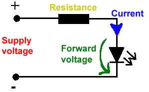
All LEDs require current limiting, without a current limiting mechanism the LED will usually burn out in under a second. Adding a simple resistor is the easiest way to limit the current. Use the calculator below to find out the value of resistor you require.

For example if you are wanting to power one of our_blank">red LEDs in an automotive application you would see that the typical forward voltage is 2.0 Volts and the maximum continuous forward current is 30mA. Therefore you would enter 14.5, 2.0 and 30 into the Single LED calculation box. After calculating you get 470ohm 1 watt as the result. Here is a that allows you to enter a resistor value and generate the corresponding color code.

Note: For automotive applications use the actual system voltage, not 12 Volts. Most 12 Volt system actually operate at around 14.5 Volts.

Supply Voltage
VOLTS
Voltage Drop Across LED
VOLTS
Desired LED Current
MILLIAMPS


Calculated Limiting Resistor
OHMS
Nearest higher rated 10% resistor

Calculated Resistor Wattage
WATTS
Safe pick is a resistor with
power rating of (common values are .25W, .5W, and 1W)
WATTS

LEDs in series

Several leds in series with one resistor
Supply Voltage
VOLTS
Voltage Drop Across LED
VOLTS
Desired LED Current
MILLIAMPS
How many LEDs connected


Calculated Limiting Resistor
OHMS
Nearest higher rated 10% resistor

Calculated Resistor Wattage
WATTS
Safe pick is a resistor with
power rating of (common values are .25W, .5W, and 1W)
WATTS
LM317 UYGULAMA DEVRELERİ HESAPLAMASI


Çıkış Voltajı
R1 resistor

R2 resistor

R1 resistor
R2 resistor

Çıkış Voltajı


Lm317 uygulama devreleri ve detayli bilgiye Buradan ulasabilirsiniz

LM555 - ASTABLE OSCILLATOR CALCULATOR

LM555 - ASTABLE OSCILLATOR CALCULATOR
Value Of R1 Ohms Value Of R2 Ohms
Value Of C1 Microfarads
Output Time HIGH SECONDS Output Time LOW SECONDS Output Period HIGH + LOW SECONDS Output Frequency HERTZ Output Duty Cycle PERCENT
Resistor values are in Ohms (1K = 1000) - Capacitor values are in Microfarads (1uF = 1)

NOTE: The leakage currents of electrolytic capacitors will affect the actual output results of the timers. To compensate for leakage it is often better to use a higher value capacitor and lower value resistances in the timer circuits.

LM555 Astable Oscillator Circuit Diagram


LM555 - ASTABLE CAPACITOR CALCULATOR

The next calculator can find the capacitance needed for a particular output frequency if the values of R1 and R2 are known.

Value Of R1 Ohms Value Of R2 Ohms
Frequency Desired Hertz
Capacitance uF
s

VOLT AMPER OHM ve WATT HESAPLAMA

Current:
kA (kiloamps) A (amps) mA (milliamps) µA (microamps)
Voltage:
kV (kilovolts) V (volts) mV (millivolts) µV (microvolts)