11 Mart 2010 Perşembe

110820 IR-Transceiver RC5/RC6 IR-Transceiver

HEXdownloads
Download RC5-RC6_Decoder_V-1_NL.bas, de broncode voor PIC Basic
Download DECODERN.HEX(RC5/RC6 decoder) bestand om in een PIC16F628A te programmeren
DECODER.HEX,PIC 16F648A ve Yoksa  (RC5/RC6 decoder)  PIC16F628A nın kullanılması

Program 1
RC5 protokolü için ;bir tane PIC16F648 A programlanması lazımdır
PORTB.0 (pin 6) ;GND bağlı hem ikilik sisteme göre ve ondalık sisteme göre sayısal verileri hemdePORTB.0 komutta sadece sayısal değerler bağlı değil komutlar ve fonksiyonlar da verilir .Örneğin sisteme ve ses +
Program 2
Elimizde PIC 16F648 A olmayabilir RC6 Çözümlenir veHEX Dosyasını PIC16F628A. Yüklenir tek işlevli LCD nin uygun olmadığı zamanlarda 2 program işleve konur hem RC5 ve RC6 sisteminin sadece sayısal hem ikili ve ondalık değerler hemde komut LCD ekranda gözükür
LED ler
Eğer resepsiyon ya da kötü bir geçiş değeri varsa PORTA.3 yeşil LED yanar kızılötesi (IR) sinyal alındığında görmeye bağlı olarak kırmızı LED Yanar , eğer sarı LED yanarsa TSOP1736 (36KHZ = IR alıcısı kullanıldıysa bu bilgileri ihtiyaç yoktur LED'ler atlanabilir) bir 470 Ohm direnç 5 V ve + ve - bacağına bağlıbir tantal 1μF kondansatör bağlanır!


Malzeme listesi

PCB : Print 110820 (Doğal kendinden gravürlü)
LCD :HD44780 (of compatibel) 2x16 karakters
IC 1 :PIC16F628(A)
VR1: 78L05 Voltaj Regülatörü
IR :Alıcı TSOP1736
LED1, LED2, LED3 :Green, Red Yellow LED, Ø3mm
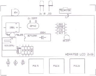
LED4, LED5: Infrareed (IR) LED, Ø5mm (bv. LD274)
T1: BC547 NPN transistor
D1: 1N4007 diode
X1: Kristal 10MHz (Düşük Tip)
R1.R3 :1k
R4 :33k
R5: 4k7
R6 :27 Ohm
R7 :470 Ohm
R8 :0,0 Ohm (Sadece küçük bir tel LCD arka işığı için bir direnç)
P1  :potansiyometre 10k...47k, 6mm,
C1 :100µF
C2 :1µF (tantaal)
C3,C4: 22pF
 SMD : 100n,(IC  pcb ye üstten lehimlenen)
Kontakt pasta
Konnektör  3,5mm


Hiç yorum yok:

Yorum Gönder

İzleyiciler

LED DİRENÇ HESAPLAMA

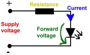
All LEDs require current limiting, without a current limiting mechanism the LED will usually burn out in under a second. Adding a simple resistor is the easiest way to limit the current. Use the calculator below to find out the value of resistor you require.

For example if you are wanting to power one of our_blank">red LEDs in an automotive application you would see that the typical forward voltage is 2.0 Volts and the maximum continuous forward current is 30mA. Therefore you would enter 14.5, 2.0 and 30 into the Single LED calculation box. After calculating you get 470ohm 1 watt as the result. Here is a that allows you to enter a resistor value and generate the corresponding color code.

Note: For automotive applications use the actual system voltage, not 12 Volts. Most 12 Volt system actually operate at around 14.5 Volts.

Supply Voltage
VOLTS
Voltage Drop Across LED
VOLTS
Desired LED Current
MILLIAMPS


Calculated Limiting Resistor
OHMS
Nearest higher rated 10% resistor

Calculated Resistor Wattage
WATTS
Safe pick is a resistor with
power rating of (common values are .25W, .5W, and 1W)
WATTS

LEDs in series

Several leds in series with one resistor
Supply Voltage
VOLTS
Voltage Drop Across LED
VOLTS
Desired LED Current
MILLIAMPS
How many LEDs connected


Calculated Limiting Resistor
OHMS
Nearest higher rated 10% resistor

Calculated Resistor Wattage
WATTS
Safe pick is a resistor with
power rating of (common values are .25W, .5W, and 1W)
WATTS
LM317 UYGULAMA DEVRELERİ HESAPLAMASI


Çıkış Voltajı
R1 resistor

R2 resistor

R1 resistor
R2 resistor

Çıkış Voltajı


Lm317 uygulama devreleri ve detayli bilgiye Buradan ulasabilirsiniz

LM555 - ASTABLE OSCILLATOR CALCULATOR

LM555 - ASTABLE OSCILLATOR CALCULATOR
Value Of R1 Ohms Value Of R2 Ohms
Value Of C1 Microfarads
Output Time HIGH SECONDS Output Time LOW SECONDS Output Period HIGH + LOW SECONDS Output Frequency HERTZ Output Duty Cycle PERCENT
Resistor values are in Ohms (1K = 1000) - Capacitor values are in Microfarads (1uF = 1)

NOTE: The leakage currents of electrolytic capacitors will affect the actual output results of the timers. To compensate for leakage it is often better to use a higher value capacitor and lower value resistances in the timer circuits.

LM555 Astable Oscillator Circuit Diagram


LM555 - ASTABLE CAPACITOR CALCULATOR

The next calculator can find the capacitance needed for a particular output frequency if the values of R1 and R2 are known.

Value Of R1 Ohms Value Of R2 Ohms
Frequency Desired Hertz
Capacitance uF
s

VOLT AMPER OHM ve WATT HESAPLAMA

Current:
kA (kiloamps) A (amps) mA (milliamps) µA (microamps)
Voltage:
kV (kilovolts) V (volts) mV (millivolts) µV (microvolts)