20 Şubat 2010 Cumartesi

IR2156, IR21571, IR21592, IR21593, IR2166, IR2167, IR2520D, IR2161, IRS2158D, IRS2166D, IRS2530D Elektronik Balast


Elektronik Balast Tasarımı


IR International rectifier firması özellikle güç elektroniği konusunda kaliteli ürünler üretiyor mosfetler. smps, pwm sürücüler vb. Bunların yanı sıra elektronik balast devrelerinde kullanılabilen ürettikleri IR, IRS entegreler için balast tasarım programı hazırlamışlar


Balast Tasarım Programı Hakkında Özetler


Tasarım yapılabilen entegreler


  1.  IR2156 (CFL Balast)
  2.  IRS2166D (Tek entegre balast)
  3.  IRS2168D (Tek entegre balast)
  4.  IR21592 (Dimmer balast)
  5.  IRS21571D (Balast)
  6.  IRS2158D (Dimmer balast)
  7.  IR2161 (Halojen kontrol)
  8.  IR2520D (Balast)
  9.  IRS2530D (DIM8 Balast)


Kullanım Bilgileri

Programın kullanımı kolay kurulumdan sonra “Ballast Designer V4” kısa yoluna tıklayıp 

Not: Masa üstünde kısa yol simgesi oluşmaz ise C:\Program Files\Ballast Designer V4\BDA.exe dosyasını çalıştırın

Programın menüsünde yapacağınız ayarlara göre otomatik olarak balast tasarımı oluşuyor

IC: Entegre seçim bölümü

Input: Giriş voltajı


Lamp: Lamba güç ve model

Configration: Paralel seri bağlantı

İsterseniz “Advanced” bölümünden ayrıntılı bir tasarım oluşturabilirsiniz bu bölüm uzman kişiler için tüm değerler elle girilebiliyor

Tüm ayarlar yapılıp “Desng 5” butonuna tıklandıktan sonra devre şeması, malzeme listesi, balast trafo nüve bilgileri, frekans voltaj eğrisi, gibi bilgiler yeni pencereler içinde görünüyor


Notlar ipuçları


Ayrıca programın çok iyi bir özelliği de gereken tasarımlara PFC devresi eklemesi ve bu PFC devresinin trafo nüve hesaplarını vermesi PFC için kullanılan entegre ST Microelectronics ürünü L6562


Program gayet başarılı özellikle trafo hesaplaması diğer kontrol entegreleri ya da sistemler için kullanılabilir diğer hesaplamalarda işinize yarayabilir firma kendi entegrelerine göre programı hazırlamış ama farklı bir entegreyi aynı frekansta çalıştırıp trafo hesabı kullanılabilir.


Denemelerde bir kere BDA.exe çalıştırldığında programın çalışmadığını gördüm görev yöneticisinde çalışıyor görünüyordu ama kendisi ortalıkta yoktu bu tip bir sorun olur ise style="color: maroon;">C:\Program Files\Ballast Designer V4\ içinde config.ini dosyasını silin program sorunsuz çalışacak tekrar ini dosyasını oluşturacak


  1. Step Ballast Design
  2. Lamp Browser
  3. Design Browser
  4. Advanced Display Page
  5. Ballast Operating Points Calculation
  6. LC Tank Component Calculator
  7. Ballast Operating Points Graph
  8. IC Component Calculator
  9. Time Domain Graph
  10. Inductor Designer
  11. Windows-based Graphical Interface
  12. PFC Component Calculator
  13. IR2156, IR21571, IR21592, IR21593, IR2166, IR2167, IR2520D, IR2161, IRS2158D, IRS2166D, IRS2530D Component Calculator Schematic
  14. Bill of Materials
  15. Electrical Data Table
  16. Inductor Specification Sheet
  17. Component Value Table
  18. Operates on Windows XP and Vista
  19. >Elektronik Programlar Hesaplama Çevirici Kod vb

Hiç yorum yok:

Yorum Gönder

İzleyiciler

LED DİRENÇ HESAPLAMA

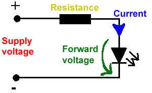
All LEDs require current limiting, without a current limiting mechanism the LED will usually burn out in under a second. Adding a simple resistor is the easiest way to limit the current. Use the calculator below to find out the value of resistor you require.

For example if you are wanting to power one of our_blank">red LEDs in an automotive application you would see that the typical forward voltage is 2.0 Volts and the maximum continuous forward current is 30mA. Therefore you would enter 14.5, 2.0 and 30 into the Single LED calculation box. After calculating you get 470ohm 1 watt as the result. Here is a that allows you to enter a resistor value and generate the corresponding color code.

Note: For automotive applications use the actual system voltage, not 12 Volts. Most 12 Volt system actually operate at around 14.5 Volts.

Supply Voltage
VOLTS
Voltage Drop Across LED
VOLTS
Desired LED Current
MILLIAMPS


Calculated Limiting Resistor
OHMS
Nearest higher rated 10% resistor

Calculated Resistor Wattage
WATTS
Safe pick is a resistor with
power rating of (common values are .25W, .5W, and 1W)
WATTS

LEDs in series

Several leds in series with one resistor
Supply Voltage
VOLTS
Voltage Drop Across LED
VOLTS
Desired LED Current
MILLIAMPS
How many LEDs connected


Calculated Limiting Resistor
OHMS
Nearest higher rated 10% resistor

Calculated Resistor Wattage
WATTS
Safe pick is a resistor with
power rating of (common values are .25W, .5W, and 1W)
WATTS
LM317 UYGULAMA DEVRELERİ HESAPLAMASI


Çıkış Voltajı
R1 resistor

R2 resistor

R1 resistor
R2 resistor

Çıkış Voltajı


Lm317 uygulama devreleri ve detayli bilgiye Buradan ulasabilirsiniz

LM555 - ASTABLE OSCILLATOR CALCULATOR

LM555 - ASTABLE OSCILLATOR CALCULATOR
Value Of R1 Ohms Value Of R2 Ohms
Value Of C1 Microfarads
Output Time HIGH SECONDS Output Time LOW SECONDS Output Period HIGH + LOW SECONDS Output Frequency HERTZ Output Duty Cycle PERCENT
Resistor values are in Ohms (1K = 1000) - Capacitor values are in Microfarads (1uF = 1)

NOTE: The leakage currents of electrolytic capacitors will affect the actual output results of the timers. To compensate for leakage it is often better to use a higher value capacitor and lower value resistances in the timer circuits.

LM555 Astable Oscillator Circuit Diagram


LM555 - ASTABLE CAPACITOR CALCULATOR

The next calculator can find the capacitance needed for a particular output frequency if the values of R1 and R2 are known.

Value Of R1 Ohms Value Of R2 Ohms
Frequency Desired Hertz
Capacitance uF
s

VOLT AMPER OHM ve WATT HESAPLAMA

Current:
kA (kiloamps) A (amps) mA (milliamps) µA (microamps)
Voltage:
kV (kilovolts) V (volts) mV (millivolts) µV (microvolts)