29 Kasım 2010 Pazartesi

Settings for MakInterface Pro Programmer


Settings for MakInterface Pro Programmer

You need the following settings:

24Cxx( I2C EEPROM)
Jumper settings
+--------------------+
| ooooo :::::::::: + |
| ooooo IIIIIII:I: - |
+--------------------+
- No Power supply required.
- Verifyed with: 24C01, 24C02, 24C04, 24C16, 24C32, 24C256
Pin4=A0+A1+A2+VSS+WP
Pin5+Pin7=SDA
Pin6=SCL
Pin8=VCC
25xxx( SPI EEPROM )
Jumper settings
+--------------------+
| ooooo ::I::::::: + |
| ooooo II:IIII:I: - |
+--------------------+
- No Power supply required.
- Verifyed with: 25020
Pin2=CS
Pin3=WP+HOLD
Pin4=GND
Pin5=SO
Pin6=SCK
Pin7=SI
Pin8=VCC
59Cxx(4-wireEEPROM)
Jumper settings
+--------------------+
| ooooo ::I::::::: + |
| ooooo II:IIII:I: - |
+--------------------+
- No Power supply required.
- Verifyed with: 59C11
Pin2=CS
Pin3=ORG
Pin4=VSS
Pin5=DO
Pin6=CLK
Pin7=DI
Pin8=VCC
93Cxx( MicrowireEEPROM )
Jumper settings
+--------------------+
| ooooo :::::::::: + |
| ooooo IIIIIII:I: - |
+--------------------+
- No Power supply required.
- Verifyed with: 93C06, 93C46, 93C66
Pin2=S
Pin4=VSS
Pin5=DO
Pin6=CLK
Pin7=DI
Pin8=VCC


AT89Sxx( Microcontroller )
Jumper settings
+--------------------+
| ooooo :::::;:::: + |
| ooooo IIIIII::I: - |
+--------------------+
- Power supply required
- Verifyed with 89S53
- Verifyed with 3.579MHz, 6MHz and 8MHz Quarz
Pin2= RST
Pin4= GND
Pin5= MISO
Pin6= SCK
Pin7= MOSI
Pin8= VCC
Pin,= XTAL1
PIC12C50x (Microcontroller)Jumper settings
+--------------------+
| ooooo :::::::::: + |
| ooooo IIIIIII:I: - |
+--------------------+
- No power supply required
- Verifyed with 12C508/9
Pin4= VSS
Pin5+Pin7= GP0
Pin6= GP1
Pin8= VSS
Pin9= MCLR/VPP
PIC16Fxx( Microcontroller )
Jumper settings
+--------------------+
| ooooo :::::::::: + |
| ooooo IIIIIII:I: - |
+--------------------+
- No power supply required
- Verifyed with 16F84/84A
Pin4= VSS
Pin5+Pin7= RB7
Pin6= RB6
Pin8= VDD
Pin9= MCLR

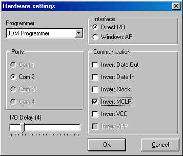
For the other PIC Microcontrollers please consult the Microchip Datasheets for the Pinout and connection. The IC-Prog Hardware setup and the Makinterface Jumper settings are the same.
For additional information you can contact MakInterface

Hiç yorum yok:

Yorum Gönder

İzleyiciler

LED DİRENÇ HESAPLAMA

All LEDs require current limiting, without a current limiting mechanism the LED will usually burn out in under a second. Adding a simple resistor is the easiest way to limit the current. Use the calculator below to find out the value of resistor you require.

For example if you are wanting to power one of our_blank">red LEDs in an automotive application you would see that the typical forward voltage is 2.0 Volts and the maximum continuous forward current is 30mA. Therefore you would enter 14.5, 2.0 and 30 into the Single LED calculation box. After calculating you get 470ohm 1 watt as the result. Here is a that allows you to enter a resistor value and generate the corresponding color code.

Note: For automotive applications use the actual system voltage, not 12 Volts. Most 12 Volt system actually operate at around 14.5 Volts.

Supply Voltage
VOLTS
Voltage Drop Across LED
VOLTS
Desired LED Current
MILLIAMPS


Calculated Limiting Resistor
OHMS
Nearest higher rated 10% resistor

Calculated Resistor Wattage
WATTS
Safe pick is a resistor with
power rating of (common values are .25W, .5W, and 1W)
WATTS

LEDs in series

Several leds in series with one resistor
Supply Voltage
VOLTS
Voltage Drop Across LED
VOLTS
Desired LED Current
MILLIAMPS
How many LEDs connected


Calculated Limiting Resistor
OHMS
Nearest higher rated 10% resistor

Calculated Resistor Wattage
WATTS
Safe pick is a resistor with
power rating of (common values are .25W, .5W, and 1W)
WATTS
LM317 UYGULAMA DEVRELERİ HESAPLAMASI


Çıkış Voltajı
R1 resistor

R2 resistor

R1 resistor
R2 resistor

Çıkış Voltajı


Lm317 uygulama devreleri ve detayli bilgiye Buradan ulasabilirsiniz

LM555 - ASTABLE OSCILLATOR CALCULATOR

LM555 - ASTABLE OSCILLATOR CALCULATOR
Value Of R1 Ohms Value Of R2 Ohms
Value Of C1 Microfarads
Output Time HIGH SECONDS Output Time LOW SECONDS Output Period HIGH + LOW SECONDS Output Frequency HERTZ Output Duty Cycle PERCENT
Resistor values are in Ohms (1K = 1000) - Capacitor values are in Microfarads (1uF = 1)

NOTE: The leakage currents of electrolytic capacitors will affect the actual output results of the timers. To compensate for leakage it is often better to use a higher value capacitor and lower value resistances in the timer circuits.

LM555 Astable Oscillator Circuit Diagram


LM555 - ASTABLE CAPACITOR CALCULATOR

The next calculator can find the capacitance needed for a particular output frequency if the values of R1 and R2 are known.

Value Of R1 Ohms Value Of R2 Ohms
Frequency Desired Hertz
Capacitance uF
s

VOLT AMPER OHM ve WATT HESAPLAMA

Current:
kA (kiloamps) A (amps) mA (milliamps) µA (microamps)
Voltage:
kV (kilovolts) V (volts) mV (millivolts) µV (microvolts)