29 Eylül 2010 Çarşamba

LED ve Infra Led Yapısı

LED
Yapısı :
Led’ler (Light Emiting Diode) yani ışık yayan diyotlar yapı itibari ile elektrik enerjisini ışığa çeviren kimyasal maddelerden oluşurlar. Kullanılan kimyasal maddedin türüne göre farklı renkte ışık verirler. Örneğin galyum fosfid kullanlan LED’ler yeşil ışık verir. Galyum fosfid’e oksijen ve çinko karıştırılarak yapılan LED’ler kırmızı ışık verir. Bunun yanında Galyum arsenid kullanılarak yapılan led’ler ise kızıl ötesi ışık verirler. Led’lerin çalışma voltajları içinde kullanılan maddeye göre değişiklik gösterir. Kızıl ötesi ışık veren bir led’in çalışma voltajı 1.4V iken yeşil ışık veren led’in çalışma voltajı 2.26V’dur.
Led’lerin bu çalışma gerilimi aşıldığında içindeki kimyasal maddenin gireceği reaksiyondan dolayı led bozulur. Bu yüzden çalışma gerilimini aşan bir voltaj uygulanacağı zaman uygun bir direnç ile led korunmalıdır.
Led’ler genellikle endüstriyel ve amatör elektronik alanında ikaz ve görsel efektler amacıyla kullanılır. Ayrıca led’ler hem DC hemde AC gerilim ile çalışabilir.
Alttaki resimde LED’in devre çizimlerinde kullanılan sembolü görünmektedir.
e15.gif
Sağlamlık Kontrolü :
Ohm metrenin içindeki pil kullanılarak led’lerin sağlamlık kontrolü yapılabilir. Genellikle yeni bir led’de uzun bacak anot (+), kısa bacak katot (-) ucudur. Ohm metrenin kırmızı ucu katoda, siyah ucu anoda bağlandığında led’in ışık vermesi gerekir.

Infra Led Yapısı :
Yapı itibariyle tamamen normal led’ler gibidir ancak tek farkı yaydığı ışığın insan gözüyle görülemeyecek bir frekans bandında olmasıdır. Yaklaşık 1.5V ile çalışır ve genellikle Foto transistörlerin ışık kaynağı olarak kullanılır.
Sağlamlık Kontrolü :
İnsan gözünün göremeyeciği bir ışık yaydığı için ohm metre ile Led’lerde olduğu gibi görsel bir ölçüm yapılamaz. Bunun yerine normal diyotlar gibi ölçülür. Ölçüm uçlarının bir yönünde açık devre diğer yönünde ise düşük direnç göstermelidir.

Hiç yorum yok:

Yorum Gönder

İzleyiciler

LED DİRENÇ HESAPLAMA

All LEDs require current limiting, without a current limiting mechanism the LED will usually burn out in under a second. Adding a simple resistor is the easiest way to limit the current. Use the calculator below to find out the value of resistor you require.

For example if you are wanting to power one of our_blank">red LEDs in an automotive application you would see that the typical forward voltage is 2.0 Volts and the maximum continuous forward current is 30mA. Therefore you would enter 14.5, 2.0 and 30 into the Single LED calculation box. After calculating you get 470ohm 1 watt as the result. Here is a that allows you to enter a resistor value and generate the corresponding color code.

Note: For automotive applications use the actual system voltage, not 12 Volts. Most 12 Volt system actually operate at around 14.5 Volts.
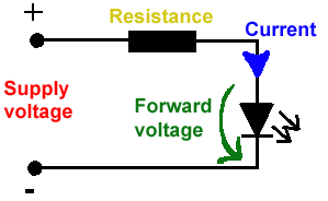
Supply Voltage
VOLTS
Voltage Drop Across LED
VOLTS
Desired LED Current
MILLIAMPS


Calculated Limiting Resistor
OHMS
Nearest higher rated 10% resistor

Calculated Resistor Wattage
WATTS
Safe pick is a resistor with
power rating of (common values are .25W, .5W, and 1W)
WATTS

LEDs in series

Several leds in series with one resistor
Supply Voltage
VOLTS
Voltage Drop Across LED
VOLTS
Desired LED Current
MILLIAMPS
How many LEDs connected


Calculated Limiting Resistor
OHMS
Nearest higher rated 10% resistor

Calculated Resistor Wattage
WATTS
Safe pick is a resistor with
power rating of (common values are .25W, .5W, and 1W)
WATTS
LM317 UYGULAMA DEVRELERİ HESAPLAMASI


Çıkış Voltajı
R1 resistor

R2 resistor

R1 resistor
R2 resistor

Çıkış Voltajı


Lm317 uygulama devreleri ve detayli bilgiye Buradan ulasabilirsiniz

LM555 - ASTABLE OSCILLATOR CALCULATOR

LM555 - ASTABLE OSCILLATOR CALCULATOR
Value Of R1 Ohms Value Of R2 Ohms
Value Of C1 Microfarads
Output Time HIGH SECONDS Output Time LOW SECONDS Output Period HIGH + LOW SECONDS Output Frequency HERTZ Output Duty Cycle PERCENT
Resistor values are in Ohms (1K = 1000) - Capacitor values are in Microfarads (1uF = 1)

NOTE: The leakage currents of electrolytic capacitors will affect the actual output results of the timers. To compensate for leakage it is often better to use a higher value capacitor and lower value resistances in the timer circuits.

LM555 Astable Oscillator Circuit Diagram


LM555 - ASTABLE CAPACITOR CALCULATOR

The next calculator can find the capacitance needed for a particular output frequency if the values of R1 and R2 are known.

Value Of R1 Ohms Value Of R2 Ohms
Frequency Desired Hertz
Capacitance uF
s

VOLT AMPER OHM ve WATT HESAPLAMA

Current:
kA (kiloamps) A (amps) mA (milliamps) µA (microamps)
Voltage:
kV (kilovolts) V (volts) mV (millivolts) µV (microvolts)