17 Eylül 2010 Cuma
Dijital Pusula
Here is the circuit diagram of a very simple and accurate electronic compass using the 1490 digital compass from Dinsmore. The 1490 digital compass is a solid state Hall Effect device which is sensitive to detect the Earth’s magnetic field. The sensor is internally damped to simulate the performance of an ordinary compass. The circuit shown here is the simplest one that can be built around this sensor.
The sensor has 12 pins at the bottom which are arranged in to four sets of three. All pins marked 1 are connected to the positive (+5V). All pins marked 2 are tied together and connected to the ground. The pins marked 3 are the output pins. Each output pin is equivalent to the open collected of an NPN transistor and can sink up to 20mA. An LED is connected between the positive (+5V) and each of the output pin. The 1K resistor will limit the LED current to 5mA.The direction can be identified by interpreting the combination of LEDs glowing. A typical 5V regulator using IC 7805 is used to produce 5V DC from the 9V battery for powering the circuit.
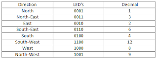
For the calibration of the compass circuit, you need an ordinary magnetic compass. Determine the North using the standard compass. Now, rotate the compass so that only one LED glows. Take this LED as the North. The sensor does not have a fixed North and you can actually use any output as the North. If the circuit is wired exactly as show in circuit diagram, the other three outputs will also fall in the proper sequence. In my circuit the LED D4 was the North. Rotating the digital compass in the clock wise direction will make the LEDs to glow in the following sequence where 1=ON and 0=OFF.
Circuit diagram.
Notes.
Assemble the circuit a good quality PCB.
Using sub miniature LEDs will increase the battery life.
The circuit can be powered from a 9V PP3 battery.
Ferrous materials close to the sensor will affect its performance.
Read more: http://www.circuitstoday.com/category/sensor-circuits#ixzz0zoUtArHW
Under Creative Commons License: Attribution
İzleyiciler
TIMING CALCULATORS FOR THE LM555
TIMING CALCULATORS FOR THE LM555
LED DİRENÇ HESAPLAMA
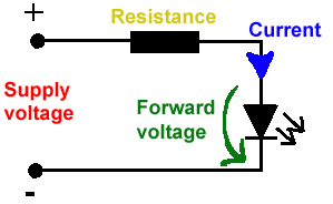
All LEDs require current limiting, without a current limiting mechanism the LED will usually burn out in under a second. Adding a simple resistor is the easiest way to limit the current. Use the calculator below to find out the value of resistor you require.
For example if you are wanting to power one of our_blank">red LEDs in an automotive application you would see that the typical forward voltage is 2.0 Volts and the maximum continuous forward current is 30mA. Therefore you would enter 14.5, 2.0 and 30 into the Single LED calculation box. After calculating you get 470ohm 1 watt as the result. Here is a that allows you to enter a resistor value and generate the corresponding color code.
Note: For automotive applications use the actual system voltage, not 12 Volts. Most 12 Volt system actually operate at around 14.5 Volts.

| Lm317 uygulama devreleri ve detayli bilgiye Buradan ulasabilirsiniz |
LM555 - ASTABLE OSCILLATOR CALCULATOR
NOTE: The leakage currents of electrolytic capacitors will affect the actual output results of the timers. To compensate for leakage it is often better to use a higher value capacitor and lower value resistances in the timer circuits.
LM555 Astable Oscillator Circuit Diagram
The next calculator can find the capacitance needed for a particular output frequency if the values of R1 and R2 are known.
| Value Of R1 Ohms | Value Of R2 Ohms |
| Frequency Desired Hertz |
|
| |
|
VOLT AMPER OHM ve WATT HESAPLAMA


Hiç yorum yok:
Yorum Gönder