4 Mayıs 2010 Salı

Mini-Crossover


Mini-Crossover


To make a regular straight through ethernet cable into a crossover we will create a mini cable a couple inches long to flip the nessicary wires and add it to the regular cable with the couple. The first thing to do is strip the outer shielding and crimp on the RJ45 plug with the following connections:

SIDE 1
RJ45 Pin1: white-orange
RJ45 Pin2: orange
RJ45 Pin3: white-green
RJ45 Pin4: blue
RJ45 Pin5: white-blue
RJ45 Pin6: green
RJ45 Pin7: white-brown
RJ45 Pin8: brown

SIDE 2
RJ45 Pin1: white-green
RJ45 Pin2: green
RJ45 Pin3: white-orange
RJ45 Pin4: white-brown
RJ45 Pin5: brown
RJ45 Pin6: orange
RJ45 Pin7: blue
RJ45 Pin8: white-blue 


Wire the DB9 Plugs

The two DB9 plugs that i found were male and we need female, so we have to convert them. The first thing to do is open the housing, there should be four clips that hold the two halves together. Once inside the case you can remove the guts of the plug and cut off the plug we wont be using. We can then solder these wires into the proper order: 


RJ45 Pin1 (blue): DB9 Pin3
RJ45 Pin2 (orange): DB9 Pin5
RJ45 Pin3 (black): DB9 Pin2
RJ45 Pin4 (red): DB9 Pin7
RJ45 Pin5 (green): DB9 Pin4
RJ45 Pin6 (yellow): DB9 Pin5
RJ45 Pin7 (brown): DB9 Pin8
RJ45 Pin8 (white): DB9 Pin1 and DB9 Pin6 

Hiç yorum yok:

Yorum Gönder

İzleyiciler

LED DİRENÇ HESAPLAMA

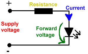
All LEDs require current limiting, without a current limiting mechanism the LED will usually burn out in under a second. Adding a simple resistor is the easiest way to limit the current. Use the calculator below to find out the value of resistor you require.

For example if you are wanting to power one of our_blank">red LEDs in an automotive application you would see that the typical forward voltage is 2.0 Volts and the maximum continuous forward current is 30mA. Therefore you would enter 14.5, 2.0 and 30 into the Single LED calculation box. After calculating you get 470ohm 1 watt as the result. Here is a that allows you to enter a resistor value and generate the corresponding color code.

Note: For automotive applications use the actual system voltage, not 12 Volts. Most 12 Volt system actually operate at around 14.5 Volts.

Supply Voltage
VOLTS
Voltage Drop Across LED
VOLTS
Desired LED Current
MILLIAMPS


Calculated Limiting Resistor
OHMS
Nearest higher rated 10% resistor

Calculated Resistor Wattage
WATTS
Safe pick is a resistor with
power rating of (common values are .25W, .5W, and 1W)
WATTS

LEDs in series

Several leds in series with one resistor
Supply Voltage
VOLTS
Voltage Drop Across LED
VOLTS
Desired LED Current
MILLIAMPS
How many LEDs connected


Calculated Limiting Resistor
OHMS
Nearest higher rated 10% resistor

Calculated Resistor Wattage
WATTS
Safe pick is a resistor with
power rating of (common values are .25W, .5W, and 1W)
WATTS
LM317 UYGULAMA DEVRELERİ HESAPLAMASI


Çıkış Voltajı
R1 resistor

R2 resistor

R1 resistor
R2 resistor

Çıkış Voltajı


Lm317 uygulama devreleri ve detayli bilgiye Buradan ulasabilirsiniz

LM555 - ASTABLE OSCILLATOR CALCULATOR

LM555 - ASTABLE OSCILLATOR CALCULATOR
Value Of R1 Ohms Value Of R2 Ohms
Value Of C1 Microfarads
Output Time HIGH SECONDS Output Time LOW SECONDS Output Period HIGH + LOW SECONDS Output Frequency HERTZ Output Duty Cycle PERCENT
Resistor values are in Ohms (1K = 1000) - Capacitor values are in Microfarads (1uF = 1)

NOTE: The leakage currents of electrolytic capacitors will affect the actual output results of the timers. To compensate for leakage it is often better to use a higher value capacitor and lower value resistances in the timer circuits.

LM555 Astable Oscillator Circuit Diagram


LM555 - ASTABLE CAPACITOR CALCULATOR

The next calculator can find the capacitance needed for a particular output frequency if the values of R1 and R2 are known.

Value Of R1 Ohms Value Of R2 Ohms
Frequency Desired Hertz
Capacitance uF
s

VOLT AMPER OHM ve WATT HESAPLAMA

Current:
kA (kiloamps) A (amps) mA (milliamps) µA (microamps)
Voltage:
kV (kilovolts) V (volts) mV (millivolts) µV (microvolts)