10 Mayıs 2010 Pazartesi

Electronic Speed Controller

This ESC is based on Mike Norton's design. I have modified the PCB to accept two FETs, which increases current capacity to more than 20 Amps.


The circuit is quite simple, as all the hard work is done inside a PIC
microcontroller. Brake and BEC (Battery Eliminator Circuit) are optional.
Cutoff voltage is set by choosing the value of resistor R7. The Schottky diode
(1N5821 or equivalent) is now mounted directly on the PCB, instead of on the motor.


My PCB layout prints actual size at 600dpi, or double-size at 300dpi. To get
the image, click on the small preview to the left, then Right-click on the
full-size image and choose "save picture as..". If you can't get it to print
the correct size, download this zip file which
contains 300dpi and 600dpi BitMap versions. These should print actual size
using Kodak Imaging for Windows


Added 25th Nov, 2003. Due to popular demand, a colourful overlay diagram showing component placement and wiring!

Value of R7 for Different Cutoff Voltages


Cells


Nom. Volts


Cutoff Volts


R7

5

6V

4.5V

760 Ohms

6

7.2V

5.4V

390 Ohms

7

8.4V

6.3V

wire link


Modifications for 4.8V operation (4 cells and no BEC)


  1. Replace IC2 (LM2940 regulator) with a 15 Ohm resistor from I to O.

  2. R7 = 330 Ohms.

  3. R8 = 2.7V 500mW Zener Diode (or 2 x 1N4148 diodes and a red LED in series).

  4. Power the Receiver (and servos) directly from the ON/OFF Switch.
Update: 23rd August, 2001
I have modified the firmware to improve glitch handling. I also replaced the Brake indicator LED with an audible arming indicator. The new source codes are spd400.asm and spd400.inc . The new hex file is SPD400.HEX .
The graph at right shows throttle response (click on it to see a more detailed plot). Note how the PWM ratio (colored black) is curved. This seems to concentrate most of the control at the lower end, but power is proportional to PWM squared, so the motor's response (purple) is linear. Throttle control is more natural using this reverse-exponential compensation. You can see that center stick (1.5mS) produces 50% power, wheras a non-compensated throttle would only produce 25% at this setting. The flat areas at 0% and 100% power are quite large, to ensure that full throttle range is available on transmitters that cannot generate the whole 1mS to 2mS servo pulse range. Notice the 'step' effect in the graph lines. This is due to the limited number of PWM ratios that can be generated (there are 40 steps).
Parts Substitutions added 14th April 2004
Q1 can be replaced with any enhancement mode PMOSFET which can handle at least 20V and has RDSon of 0.1 Ohms or lower, eg. 2SJ255. Q2 and Q3 are NMOSFETs with logic level gate drive (must turn on with 4.5V or less), VDss = 30V or better, and RDSon lower than 0.01 Ohms. I have used the HUF76143. Other good choices are the IRL3803 or SUP75N03-04. You could use two cheap FETs in parallel to get a low enough RDSon, eg. 2 x IRL3103 = 0.008 Ohms.
Schottky diode D1 should be rated at least 3A and 20V. Q4 can be replaced with a 2N7000 or equivalent. Q5 can be just about any PNP low power transistor, eg. BC327, 2N3906. IC2 must be a low dropout voltage 5V regulator, if you want to use a 6 or 7 cell battery (the standard 7805 regulator has a dropout voltage of 7V, so needs 8 cells or more). I use the ROHM BA05T. Check the pinouts, some regulators have input and output pins reversed!
If you want to modify the source code, a Flash PIC will save lots of money (the 12C509 can only be programmed once unless you get the expensive windowed verison). The 12F629 and 12F675 are pin compatible, and just need slightly modified coding (spd475.zip

Hiç yorum yok:

Yorum Gönder

İzleyiciler

LED DİRENÇ HESAPLAMA

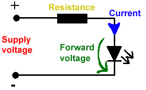
All LEDs require current limiting, without a current limiting mechanism the LED will usually burn out in under a second. Adding a simple resistor is the easiest way to limit the current. Use the calculator below to find out the value of resistor you require.

For example if you are wanting to power one of our_blank">red LEDs in an automotive application you would see that the typical forward voltage is 2.0 Volts and the maximum continuous forward current is 30mA. Therefore you would enter 14.5, 2.0 and 30 into the Single LED calculation box. After calculating you get 470ohm 1 watt as the result. Here is a that allows you to enter a resistor value and generate the corresponding color code.

Note: For automotive applications use the actual system voltage, not 12 Volts. Most 12 Volt system actually operate at around 14.5 Volts.

Supply Voltage
VOLTS
Voltage Drop Across LED
VOLTS
Desired LED Current
MILLIAMPS


Calculated Limiting Resistor
OHMS
Nearest higher rated 10% resistor

Calculated Resistor Wattage
WATTS
Safe pick is a resistor with
power rating of (common values are .25W, .5W, and 1W)
WATTS

LEDs in series

Several leds in series with one resistor
Supply Voltage
VOLTS
Voltage Drop Across LED
VOLTS
Desired LED Current
MILLIAMPS
How many LEDs connected


Calculated Limiting Resistor
OHMS
Nearest higher rated 10% resistor

Calculated Resistor Wattage
WATTS
Safe pick is a resistor with
power rating of (common values are .25W, .5W, and 1W)
WATTS
LM317 UYGULAMA DEVRELERİ HESAPLAMASI


Çıkış Voltajı
R1 resistor

R2 resistor

R1 resistor
R2 resistor

Çıkış Voltajı


Lm317 uygulama devreleri ve detayli bilgiye Buradan ulasabilirsiniz

LM555 - ASTABLE OSCILLATOR CALCULATOR

LM555 - ASTABLE OSCILLATOR CALCULATOR
Value Of R1 Ohms Value Of R2 Ohms
Value Of C1 Microfarads
Output Time HIGH SECONDS Output Time LOW SECONDS Output Period HIGH + LOW SECONDS Output Frequency HERTZ Output Duty Cycle PERCENT
Resistor values are in Ohms (1K = 1000) - Capacitor values are in Microfarads (1uF = 1)

NOTE: The leakage currents of electrolytic capacitors will affect the actual output results of the timers. To compensate for leakage it is often better to use a higher value capacitor and lower value resistances in the timer circuits.

LM555 Astable Oscillator Circuit Diagram


LM555 - ASTABLE CAPACITOR CALCULATOR

The next calculator can find the capacitance needed for a particular output frequency if the values of R1 and R2 are known.

Value Of R1 Ohms Value Of R2 Ohms
Frequency Desired Hertz
Capacitance uF
s

VOLT AMPER OHM ve WATT HESAPLAMA

Current:
kA (kiloamps) A (amps) mA (milliamps) µA (microamps)
Voltage:
kV (kilovolts) V (volts) mV (millivolts) µV (microvolts)