14 Nisan 2010 Çarşamba

SCR ALARM DEVRESİ


Sizin için faydalı olacağını düşündüğüm bir alarm devresi malzemeler şekillerin üzerinde yazılı
bu devreleri yapmak isteyenler teknik personel olacağından ingilizce metni Türkçe ye çevirmedim bunun böyle olması bence daha sağlıklı olabilir biraz sizi uğraştıracak olsada sizin daha iyi anlamanızı da sağlar sanırım

It's easy to use. When you switch on the alarm - you have about 30 seconds to leave the building. When you return and open the door - the Buzzer will sound. You have about 30 seconds to switch off the alarm.


 If you fail to do so - the Siren will sound.After about 10 minutes - the alarm will attempt to reset itself. If the trigger circuit has been restored - the attempt will be successful. But - if the loop is still open - the attempt will fail - and the alarm will re-activate. Of course - you can turn the Siren off at any time by switching off the alarm.


A conventional bell uses up to about 400ma. An electronic siren generally uses less. If you intend to draw a heavier current from either the Buzzer or Siren terminals - the SCR in question will need to be bolted to a metal heatsink - and the relay contacts may need upgrading.If you don't want the timed "cut-off and reset" feature - leave out D5, D6, R11, R12, Q3, Q4, C6 and the Relay.Because of manufacturing tolerances - the precise length of any delay depends on the characteristics of the actual components you've used in your circuit. But - to some degree - by altering the values of R2, R7 & R11 you can adjust the Exit, Entry and Reset times to suit your requirements. Increasing the values increases the time - and vice-versa.

Hiç yorum yok:

Yorum Gönder

İzleyiciler

LED DİRENÇ HESAPLAMA

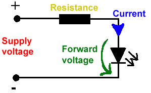
All LEDs require current limiting, without a current limiting mechanism the LED will usually burn out in under a second. Adding a simple resistor is the easiest way to limit the current. Use the calculator below to find out the value of resistor you require.

For example if you are wanting to power one of our_blank">red LEDs in an automotive application you would see that the typical forward voltage is 2.0 Volts and the maximum continuous forward current is 30mA. Therefore you would enter 14.5, 2.0 and 30 into the Single LED calculation box. After calculating you get 470ohm 1 watt as the result. Here is a that allows you to enter a resistor value and generate the corresponding color code.

Note: For automotive applications use the actual system voltage, not 12 Volts. Most 12 Volt system actually operate at around 14.5 Volts.

Supply Voltage
VOLTS
Voltage Drop Across LED
VOLTS
Desired LED Current
MILLIAMPS


Calculated Limiting Resistor
OHMS
Nearest higher rated 10% resistor

Calculated Resistor Wattage
WATTS
Safe pick is a resistor with
power rating of (common values are .25W, .5W, and 1W)
WATTS

LEDs in series

Several leds in series with one resistor
Supply Voltage
VOLTS
Voltage Drop Across LED
VOLTS
Desired LED Current
MILLIAMPS
How many LEDs connected


Calculated Limiting Resistor
OHMS
Nearest higher rated 10% resistor

Calculated Resistor Wattage
WATTS
Safe pick is a resistor with
power rating of (common values are .25W, .5W, and 1W)
WATTS
LM317 UYGULAMA DEVRELERİ HESAPLAMASI


Çıkış Voltajı
R1 resistor

R2 resistor

R1 resistor
R2 resistor

Çıkış Voltajı


Lm317 uygulama devreleri ve detayli bilgiye Buradan ulasabilirsiniz

LM555 - ASTABLE OSCILLATOR CALCULATOR

LM555 - ASTABLE OSCILLATOR CALCULATOR
Value Of R1 Ohms Value Of R2 Ohms
Value Of C1 Microfarads
Output Time HIGH SECONDS Output Time LOW SECONDS Output Period HIGH + LOW SECONDS Output Frequency HERTZ Output Duty Cycle PERCENT
Resistor values are in Ohms (1K = 1000) - Capacitor values are in Microfarads (1uF = 1)

NOTE: The leakage currents of electrolytic capacitors will affect the actual output results of the timers. To compensate for leakage it is often better to use a higher value capacitor and lower value resistances in the timer circuits.

LM555 Astable Oscillator Circuit Diagram


LM555 - ASTABLE CAPACITOR CALCULATOR

The next calculator can find the capacitance needed for a particular output frequency if the values of R1 and R2 are known.

Value Of R1 Ohms Value Of R2 Ohms
Frequency Desired Hertz
Capacitance uF
s

VOLT AMPER OHM ve WATT HESAPLAMA

Current:
kA (kiloamps) A (amps) mA (milliamps) µA (microamps)
Voltage:
kV (kilovolts) V (volts) mV (millivolts) µV (microvolts)