17 Nisan 2010 Cumartesi
I harfinde bulabildiğim entegreler ve nerede kulanıldıklarını gösterir liste
ICL7106CPL-MBR ADC 3.5-DIG 333ms+LCD DR.
ICL7106RCPL-MB ADC 3.5-DIG 333ms REVERSE
ICL7107CPL-MBR ADC 3.5-DIG 333ms+LED DR.
ICL7109CPL-MBR ADC 12B 133ms
ICL7116CPL-MBR ADC 3.5-DIG 333ms+DISPL H
ICL7117CPL-MBR ADC 3.5-DIG 7-SEGMENT OUT
ICL7126CPL-MBR ADC 3.5-DIG 333ms LOW-POW
ICL7129CPL-HAR IC.
ICL7135CPI-MBR ADC 4.5-DIG 250ms BCD OUT
ICL7136CPL-MBR ADC 3.5-DIG 333ms LOW-POW
ICL7611 Bakınız: TLC271CP-MBR
ICL7650CPA-MBR 1xOPAMP 2MHz CHOPPER STAB
ICL7650CPD-MBR OPAMP 1* 2MHz CHOPPER STA
ICL7662CPA-MBR SINGLE DC-to-DC CONVERTER
ICL8013CCTX 4-QUADRANT ANALOG MULTIPL
ICL8038CCPD-MB PREC.WAVEFORM GEN/VOLT CO
ICM7170IPG-MBR uPC CLOCK/CALENDAR 4MHz
ICM7207IPD-MBR CMOS TIMEBASE GENERATOR
ICM7217AIPI-MB 4-DIG U/D CNTR + LED DR
ICM7224IPL-MBR LCD-DRIVER 4.5-DIG
ICM7555CN Bakınız: NE555NCMOS-MBR
ICM7556IPD Bakınız: NE556NCMOS-MBR
ICS1700AN NiCd CHARGER I.C.
ICS1702N NiMH CHARGER IC
IR2110-IR CMOS MOTOR DRIVER
IR2E02-SHR NIXIE DISPLAY DRIVER
IR2E27A-SHR DOT MATRIX DISPLAY DRIVER
IR94559 Bakınız: RC4559N-MBR
IX0640C Bakınız: LA7830-SAN
İzleyiciler
TIMING CALCULATORS FOR THE LM555
TIMING CALCULATORS FOR THE LM555
LED DİRENÇ HESAPLAMA
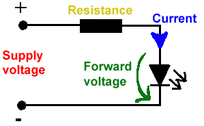
All LEDs require current limiting, without a current limiting mechanism the LED will usually burn out in under a second. Adding a simple resistor is the easiest way to limit the current. Use the calculator below to find out the value of resistor you require.
For example if you are wanting to power one of our_blank">red LEDs in an automotive application you would see that the typical forward voltage is 2.0 Volts and the maximum continuous forward current is 30mA. Therefore you would enter 14.5, 2.0 and 30 into the Single LED calculation box. After calculating you get 470ohm 1 watt as the result. Here is a that allows you to enter a resistor value and generate the corresponding color code.
Note: For automotive applications use the actual system voltage, not 12 Volts. Most 12 Volt system actually operate at around 14.5 Volts.

| Lm317 uygulama devreleri ve detayli bilgiye Buradan ulasabilirsiniz |
LM555 - ASTABLE OSCILLATOR CALCULATOR
NOTE: The leakage currents of electrolytic capacitors will affect the actual output results of the timers. To compensate for leakage it is often better to use a higher value capacitor and lower value resistances in the timer circuits.
LM555 Astable Oscillator Circuit Diagram
The next calculator can find the capacitance needed for a particular output frequency if the values of R1 and R2 are known.
| Value Of R1 Ohms | Value Of R2 Ohms |
| Frequency Desired Hertz |
|
| |
|
VOLT AMPER OHM ve WATT HESAPLAMA


Hiç yorum yok:
Yorum Gönder