28 Şubat 2010 Pazar

DÜŞÜK KAPASİTELİ HIZLI GEÇİŞLİ İZOLE DİYOT

(a) Steering diode applications
(b) LAN and WAN Networks
(c) Computer and peripheral I/O Ports
(d) Core driver switching
(e) High frequency data lines
(f) Interface networks
(a) Plastic DIP Packages
(b) Hermetic ceramic DIP Packages
(c) Flat Packages
(d) Surface Mount Packages
(e) Most Transistor (TO) type Packages


(a) Electronic Static Discharge protection (ESD)
(b) Electronic Fast Transients protection (EFT)
(c) Surge Protection
(d) Fast switching data lines
(e) Core Driver Applications
(f) Digital I/O Ports
(g) Ethernet Applications
(h) WAN Networks
(i) LAN Networks

(a) Discrete isolated diodes
(b) 10 Nanosecond reverse recovery
(c) 8 Picofarad junction capacitance
(d) High component density
(e) Improved circuit reliability
(f) Low leakage current
(g) No cross talk


Vrm = 85 Volts
Vr = 75 Volts
If = 215 mA
Tj = 150 Degrees C 

Vf (V) Ir (uA) Capacitance (pF)
Junction Diode
Trr (nS)
@100mA @500mA @Vr = 40V Vr = 0V If = Ir = 10mA
RL = 100 Ohms
1.0 1.5 0.100 2 4


FAIRCHILD TYPES

MOTOROLA TYPES
ZETEX
NATIONAL
SILICON GENERAL
TELEDY        

JEDEC


FAIRCHILD TYPES MOTOROLA TYPES ZETEX NATIONAL SILICON GENERAL TELEDYNE JEDEC
FSA2500M MAD130C BAT22 2503P SG9100F TND903 1N5768
FSA2501M MAD130P BAT22E 2503M SG6100G TND905 1N5770
FSA2501P MAD1103C BAT22J 2504M TND907 1N5772
FSA2502M MAD1103F BAT26 2509M TND908 1N5773
FSA2503M MAD1103P BAT26E 2509P TND913 1N5774
FSA2503P MAD1104C BAT26H 2510P TND921 1N5775
FSA2510M MAD1104F BAT28G TND933 1N6100
FSA2510P MAD1104P BAT28H TND938 1N6101
FSA2504M MAD1107C TND939 1N6496
FSA2504M MAD1107F TND940 1N6506
FSA2509M MAD1107P TND942 1N6507
FSA2909M MAD1108P 1N6508
FSA2565P MAD1109C 1N6509
FSA2565M MMAD130 1N6510
FSA2619P MMAD1103 1N6511
FSA2619M MMAD1104
FSA2620M MMAD1107
FSA2620P MMAD1108
FSA2621M MMAD1109
FSA2719P
FSA2719M
FSA2720M
FSA2720P
FSA2721P

Hiç yorum yok:

Yorum Gönder

İzleyiciler

LED DİRENÇ HESAPLAMA

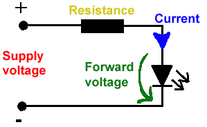
All LEDs require current limiting, without a current limiting mechanism the LED will usually burn out in under a second. Adding a simple resistor is the easiest way to limit the current. Use the calculator below to find out the value of resistor you require.

For example if you are wanting to power one of our_blank">red LEDs in an automotive application you would see that the typical forward voltage is 2.0 Volts and the maximum continuous forward current is 30mA. Therefore you would enter 14.5, 2.0 and 30 into the Single LED calculation box. After calculating you get 470ohm 1 watt as the result. Here is a that allows you to enter a resistor value and generate the corresponding color code.

Note: For automotive applications use the actual system voltage, not 12 Volts. Most 12 Volt system actually operate at around 14.5 Volts.

Supply Voltage
VOLTS
Voltage Drop Across LED
VOLTS
Desired LED Current
MILLIAMPS


Calculated Limiting Resistor
OHMS
Nearest higher rated 10% resistor

Calculated Resistor Wattage
WATTS
Safe pick is a resistor with
power rating of (common values are .25W, .5W, and 1W)
WATTS

LEDs in series

Several leds in series with one resistor
Supply Voltage
VOLTS
Voltage Drop Across LED
VOLTS
Desired LED Current
MILLIAMPS
How many LEDs connected


Calculated Limiting Resistor
OHMS
Nearest higher rated 10% resistor

Calculated Resistor Wattage
WATTS
Safe pick is a resistor with
power rating of (common values are .25W, .5W, and 1W)
WATTS
LM317 UYGULAMA DEVRELERİ HESAPLAMASI


Çıkış Voltajı
R1 resistor

R2 resistor

R1 resistor
R2 resistor

Çıkış Voltajı


Lm317 uygulama devreleri ve detayli bilgiye Buradan ulasabilirsiniz

LM555 - ASTABLE OSCILLATOR CALCULATOR

LM555 - ASTABLE OSCILLATOR CALCULATOR
Value Of R1 Ohms Value Of R2 Ohms
Value Of C1 Microfarads
Output Time HIGH SECONDS Output Time LOW SECONDS Output Period HIGH + LOW SECONDS Output Frequency HERTZ Output Duty Cycle PERCENT
Resistor values are in Ohms (1K = 1000) - Capacitor values are in Microfarads (1uF = 1)

NOTE: The leakage currents of electrolytic capacitors will affect the actual output results of the timers. To compensate for leakage it is often better to use a higher value capacitor and lower value resistances in the timer circuits.

LM555 Astable Oscillator Circuit Diagram


LM555 - ASTABLE CAPACITOR CALCULATOR

The next calculator can find the capacitance needed for a particular output frequency if the values of R1 and R2 are known.

Value Of R1 Ohms Value Of R2 Ohms
Frequency Desired Hertz
Capacitance uF
s

VOLT AMPER OHM ve WATT HESAPLAMA

Current:
kA (kiloamps) A (amps) mA (milliamps) µA (microamps)
Voltage:
kV (kilovolts) V (volts) mV (millivolts) µV (microvolts)