| Electronic Workbench Türkçe Kullanım Kılavuzu Bilgisayar Denilen insan işlerini en kolay hale getiren alet her kullanıcıya erişebildiği için .Artık üretim yapılmadan düşünülenler .Uygulamaya geçilmeden program yazanların ürettikleri programlarla bunlar malzeme ve zamandan tasaruf ederek üretime geçmeden değiştirilmesi gerekenler varsa onları değiştirmek ve en ideal devreyi üretmek artık çok kolaylaşmış ve elektronik ve tüm bilimler bu şekilde çok hızlı gelişme göstermiştir .Bir çok üreticifirma değişik programlar üretmiş olup bu tür programlar pek çoktur ancak çizimle birlikte analiz yapan program sayısı pek fazla değildir Elektronik Workbench programı bunlardan biridir .Bu programın EWB 5.12 basit kullanımıyla ön plana çıkmıştır.Bu program size çizim ve similasyonda kolaylık sağlayacaktır . | |
Yazılımı indirmek için tıklamanız yeterlidir. | |
13 Şubat 2010 Cumartesi
Electronic Workbench Similasyon Programı Türkçe kullanım Kılavuzu
İzleyiciler
TIMING CALCULATORS FOR THE LM555
TIMING CALCULATORS FOR THE LM555
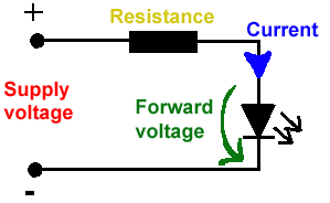
LED DİRENÇ HESAPLAMA
All LEDs require current limiting, without a current limiting mechanism the LED will usually burn out in under a second. Adding a simple resistor is the easiest way to limit the current. Use the calculator below to find out the value of resistor you require.
For example if you are wanting to power one of our_blank">red LEDs in an automotive application you would see that the typical forward voltage is 2.0 Volts and the maximum continuous forward current is 30mA. Therefore you would enter 14.5, 2.0 and 30 into the Single LED calculation box. After calculating you get 470ohm 1 watt as the result. Here is a that allows you to enter a resistor value and generate the corresponding color code.
Note: For automotive applications use the actual system voltage, not 12 Volts. Most 12 Volt system actually operate at around 14.5 Volts.

| Lm317 uygulama devreleri ve detayli bilgiye Buradan ulasabilirsiniz |
LM555 - ASTABLE OSCILLATOR CALCULATOR
NOTE: The leakage currents of electrolytic capacitors will affect the actual output results of the timers. To compensate for leakage it is often better to use a higher value capacitor and lower value resistances in the timer circuits.
LM555 Astable Oscillator Circuit Diagram
The next calculator can find the capacitance needed for a particular output frequency if the values of R1 and R2 are known.
| Value Of R1 Ohms | Value Of R2 Ohms |
| Frequency Desired Hertz |
|
| |
|
VOLT AMPER OHM ve WATT HESAPLAMA


Hiç yorum yok:
Yorum Gönder