10 Şubat 2010 Çarşamba

Tuz miktarını ayarlayan devre şeması ve Çalışması


MALZEME LİSTESİ

R1________________470R   1/4W Direnç
R2,R5______________10K   1/4WDirenç
R3,R6_____________220K   1/4WDirenç
R4__________________5K   1/2W Trimmer Cermet
R7________________680R   1/4W Direnç
R8__________________2K2  1/4WDirenç
R9,R10,R11,R12,R13__1K   1/4W Direnç

C1________________100µF   25V Elektrolytik Kondansatör
D1,D2,D3______3 or 5mm. Red LED
D4____________3 or 5mm. Green LED
D5____________3 or 5mm. Yellow LED
IC1_______________LM324 Düşük akım  Quad Op-amp
P1_________________SPST Pushbutton
Probes_________________ (metin de gösteriliyor)
B1___________________9V PP3 PİL veya Akü 
Güvenilir bir okuma elde etmek için en az 30 saniye bekleyin.
Her testten sonra probu dikkatle yıkayın ve silin.
Kurulum için  10V aralığı olan IC1A ve negatif   1 inci pine bağlı bir DC voltmetre kullanabilirsiniz Bu şekilde daha hassas okuma elde edilir.
R4  ayarlı direnci ile hassas  ayar yapabilmek için probun ucunu tatlı suya batırarak sıfır ayarı yapılır.
Size eşik gerilim seviyelerini R4   Direncinin değerini değiştirerek D3 LED i kırparak yanacaktır .  R8 değeri ni değiştirerek  D4 LED inin ayarı yapılır  ve R9 değerini değiştirerek  D5  LED inin Hassasiyet aralığını değiştirebilirsiniz.
P1 buton Yerine ortak bir SPST anahtar da koyulabilir.


IC1A op-Amp DC Akım  direnci ölçülen çıkış voltajı arttıkça  Problarda yüksekdirenç azalır taze su eklenir bu orantılı olarak artan su miktarı ile tuz miktarı azalacak ve bu tuz miktarı en az seviyede ise IC1B, IC1C ve IC1D karşılaştırıcılar sayesinde D5 LED  i Yanacak  Eğer D4 LED i Yanarsa normal tuz miktarı  D3  LED i yanarsa tuz miktarının aşırı artmış olduğunu anlarız D1 ve D2 nin  her zaman, amacı iki referans gerilimi sağlamak, böylece devre hassasiyetini artırmaktadır. D2 de istikrarlı bir tedarik 3.2V anot olmayan referans direnç zinciri R8, R9 ve R10 yoluyla karşılaştırıcıların girdiler tersini beslenir. 1.6V referans gerilim D1 anot mevcut problar ve  R4 beslenir.


Hiç yorum yok:

Yorum Gönder

İzleyiciler

LED DİRENÇ HESAPLAMA

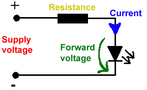
All LEDs require current limiting, without a current limiting mechanism the LED will usually burn out in under a second. Adding a simple resistor is the easiest way to limit the current. Use the calculator below to find out the value of resistor you require.

For example if you are wanting to power one of our_blank">red LEDs in an automotive application you would see that the typical forward voltage is 2.0 Volts and the maximum continuous forward current is 30mA. Therefore you would enter 14.5, 2.0 and 30 into the Single LED calculation box. After calculating you get 470ohm 1 watt as the result. Here is a that allows you to enter a resistor value and generate the corresponding color code.

Note: For automotive applications use the actual system voltage, not 12 Volts. Most 12 Volt system actually operate at around 14.5 Volts.

Supply Voltage
VOLTS
Voltage Drop Across LED
VOLTS
Desired LED Current
MILLIAMPS


Calculated Limiting Resistor
OHMS
Nearest higher rated 10% resistor

Calculated Resistor Wattage
WATTS
Safe pick is a resistor with
power rating of (common values are .25W, .5W, and 1W)
WATTS

LEDs in series

Several leds in series with one resistor
Supply Voltage
VOLTS
Voltage Drop Across LED
VOLTS
Desired LED Current
MILLIAMPS
How many LEDs connected


Calculated Limiting Resistor
OHMS
Nearest higher rated 10% resistor

Calculated Resistor Wattage
WATTS
Safe pick is a resistor with
power rating of (common values are .25W, .5W, and 1W)
WATTS
LM317 UYGULAMA DEVRELERİ HESAPLAMASI


Çıkış Voltajı
R1 resistor

R2 resistor

R1 resistor
R2 resistor

Çıkış Voltajı


Lm317 uygulama devreleri ve detayli bilgiye Buradan ulasabilirsiniz

LM555 - ASTABLE OSCILLATOR CALCULATOR

LM555 - ASTABLE OSCILLATOR CALCULATOR
Value Of R1 Ohms Value Of R2 Ohms
Value Of C1 Microfarads
Output Time HIGH SECONDS Output Time LOW SECONDS Output Period HIGH + LOW SECONDS Output Frequency HERTZ Output Duty Cycle PERCENT
Resistor values are in Ohms (1K = 1000) - Capacitor values are in Microfarads (1uF = 1)

NOTE: The leakage currents of electrolytic capacitors will affect the actual output results of the timers. To compensate for leakage it is often better to use a higher value capacitor and lower value resistances in the timer circuits.

LM555 Astable Oscillator Circuit Diagram


LM555 - ASTABLE CAPACITOR CALCULATOR

The next calculator can find the capacitance needed for a particular output frequency if the values of R1 and R2 are known.

Value Of R1 Ohms Value Of R2 Ohms
Frequency Desired Hertz
Capacitance uF
s

VOLT AMPER OHM ve WATT HESAPLAMA

Current:
kA (kiloamps) A (amps) mA (milliamps) µA (microamps)
Voltage:
kV (kilovolts) V (volts) mV (millivolts) µV (microvolts)