24 Ocak 2010 Pazar

220 Volt 12 Kw 40 A güç devresi


 Bu cihaz oldukça yüksek güçlü alıcılar ile çalıştırılmak üzere tasarlanmıştır. Kolayca 10kW ın üzerinde güç kapasitesine çıkan yüklerle çalışabilir Sistemde Triyak olarak BTA 40 -600 BRG 3 Adet kullanılmıştır bu triyaklar Soğutucu Radyötör Üstüne Monte edilmiş ve güzelce yalıtılmışlardır . Isı Radyötör üstüne dağıtılmış ve istenirse ayriyeten bir Fan’lada soğutulabilir.Bu modül 220V AC Kontaktör Bobin Yerine tasarlanmıştır. 22k lık yüksek güç direnci  Limitleri sabitleyici ve  D2 (24) V diyot  ve C1 (47uF) kondansatörün doğru Çalışması için Koşulları sağlar Aşırı voltaj a karşı C1  ve D2 koruma sağlar Çünkü üzerindeki Yük Voltajı hiçbir zaman  20 V aşmaz D1  Diyot Yeşil Led  Kumanda olarak hizmet vermektedir.R8 1k5 direnci led üzerinden OPT1 …. ve OPT3 (CNR21) optik diyotlar 
ile seri bağlantı yapılıp D1 ve D2 ,R7 diyot ve direncin üzerindeki ısıyı ve güç tüketimini basitçe azaltmak için seçildi. Dirençler R1,R6 (180R)olarak seçildi mevcut T1-T3 (BTA40) Triyakları Korumak İçin Çıkış sistemi W1-W3  VARiYAK larla (14N431)
 Korunmuş Oldu Ayriyeten Optik Korumada Mevcuttur. Sistem faz başına 12 Kw güç 
Üretir .


Variystör JVR-14N 431K. Voltaj 430V; 275VAC; 350VDC Fazla 0.60W; tolerans10%. Max. enerji po 2ms - 104.0J, Kapasite 460pF. 


 Malzeme Listesi
1.      Köprü Diyot BR1 A                       1 Adet   
2.      R1-R6 180 Ohm Direnç                  6 Adet


3.      R7 22K / 5w Taş Direnç                1 Adet
4.      R8 1K5 direnç                              1 Adet
5.      C1 47uF elektrolit                        1 Adet
6.       D2 Zener Diyot 24 Volt                1 Adet        
7.       D1 Yeşil LED                               1 Adet
8.       Opt CNR21                                  3 Adet
9.       Triyak BTA 40-600 BRG               3 Adet
10.  Variyak JVR-14N431 K                3 Adet
11.  Soğutucu Radyötör  5 *5              1 Adet
12.  1 Cm lik pın spacer                     5 Adet
13.  ARK3 Bağlantı soketi Üçlü          1 Adet
14. Çıkış İçin Konektör Bağlantısı      3 Adet


varystor JVR-14N 431K. Voltaj 430V; 275VAC; 350VDC
En çok 0.60W; tolerans 10%.
Max. enerji po 2ms - 104.0J, Potansiyel 460pF. 


Hiç yorum yok:

Yorum Gönder

İzleyiciler

LED DİRENÇ HESAPLAMA

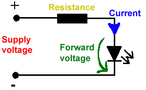
All LEDs require current limiting, without a current limiting mechanism the LED will usually burn out in under a second. Adding a simple resistor is the easiest way to limit the current. Use the calculator below to find out the value of resistor you require.

For example if you are wanting to power one of our_blank">red LEDs in an automotive application you would see that the typical forward voltage is 2.0 Volts and the maximum continuous forward current is 30mA. Therefore you would enter 14.5, 2.0 and 30 into the Single LED calculation box. After calculating you get 470ohm 1 watt as the result. Here is a that allows you to enter a resistor value and generate the corresponding color code.

Note: For automotive applications use the actual system voltage, not 12 Volts. Most 12 Volt system actually operate at around 14.5 Volts.

Supply Voltage
VOLTS
Voltage Drop Across LED
VOLTS
Desired LED Current
MILLIAMPS


Calculated Limiting Resistor
OHMS
Nearest higher rated 10% resistor

Calculated Resistor Wattage
WATTS
Safe pick is a resistor with
power rating of (common values are .25W, .5W, and 1W)
WATTS

LEDs in series

Several leds in series with one resistor
Supply Voltage
VOLTS
Voltage Drop Across LED
VOLTS
Desired LED Current
MILLIAMPS
How many LEDs connected


Calculated Limiting Resistor
OHMS
Nearest higher rated 10% resistor

Calculated Resistor Wattage
WATTS
Safe pick is a resistor with
power rating of (common values are .25W, .5W, and 1W)
WATTS
LM317 UYGULAMA DEVRELERİ HESAPLAMASI


Çıkış Voltajı
R1 resistor

R2 resistor

R1 resistor
R2 resistor

Çıkış Voltajı


Lm317 uygulama devreleri ve detayli bilgiye Buradan ulasabilirsiniz

LM555 - ASTABLE OSCILLATOR CALCULATOR

LM555 - ASTABLE OSCILLATOR CALCULATOR
Value Of R1 Ohms Value Of R2 Ohms
Value Of C1 Microfarads
Output Time HIGH SECONDS Output Time LOW SECONDS Output Period HIGH + LOW SECONDS Output Frequency HERTZ Output Duty Cycle PERCENT
Resistor values are in Ohms (1K = 1000) - Capacitor values are in Microfarads (1uF = 1)

NOTE: The leakage currents of electrolytic capacitors will affect the actual output results of the timers. To compensate for leakage it is often better to use a higher value capacitor and lower value resistances in the timer circuits.

LM555 Astable Oscillator Circuit Diagram


LM555 - ASTABLE CAPACITOR CALCULATOR

The next calculator can find the capacitance needed for a particular output frequency if the values of R1 and R2 are known.

Value Of R1 Ohms Value Of R2 Ohms
Frequency Desired Hertz
Capacitance uF
s

VOLT AMPER OHM ve WATT HESAPLAMA

Current:
kA (kiloamps) A (amps) mA (milliamps) µA (microamps)
Voltage:
kV (kilovolts) V (volts) mV (millivolts) µV (microvolts)