12 Eylül 2017 Salı

Ardiuno ile röle kullanımı

Neden Arduino kurulu bir röle kullanıyorsunuz?

Malzeme listesi

  1. Arduino uno
  2. arduino röle kiti
  3. led
  4. 220 Ohm direnç 
  5. yeteri kadar jumper kablo
  6. harici voltaj Adaptörü

Bireysel uygulamalar değişebilir, ancak kısaca - bir röle nispeten düşük voltaj Arduino'mızın daha yüksek güç devrelerini kolayca kontrol etmesini sağlar. Bir röle, bir Arduino pininden çıkan 5V'u kullanarak, daha önce adı geçen yüksek güç devresine bağlı dahili, fiziksel bir anahtarı kapatan bir elektromıknatısa enerji verir. Trafiğe karşı kullanılan Trafik işaretlerinde büyük röleler  gibi tıpkı küçük rölelerde bile kapanış * tıklama * sesini yani rölenin açılıp kapandığını  duyabilirsiniz.
arduinorelay.jpg


Arduino  röle kiti


Arduino uno ve röle (RELAY) ile led yakma devresi


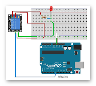
5 voltluk röle kiti ile arduino ve led in bağlantısını yapmak için rölenin + pinine +5 volt eksi yani GND ucunuda - voltaja (GND) bağlayacağız sinyal ucunuda Arduino nun dijital 8 pinine bağlayarak rölenin kontrolünü yapacağız ledin pozitif bacağından 220 Ohm direnç ile yapılacak negatif ucunuda GND  voltajına bağlayarak ledi röle ve arduino ile kontrol edeceğiz
.


// Arduinoturkiye.com Röle Kontrol Deneme Programı

// Dijital 2 pinini role olarak isimlendiriyoruz.

#define RELAY 8                // Devre şemasındaki Arduino Dijital Pin-Arduino Dijital 8 bağlantısını yapıyoruz.

void setup() {     // Role(Dijital 8)  pinini çıkış olarak ayarlıyoruz.

  
Serial.begin(115200);    // seri haberleşme 115200 hızı ile başlatılmıştır.
pinMode(RELAY, OUTPUT);
}
 

void loop() {       // Role(Dijital 2 pinini HIGH olarak tanımlıyoruz, yani roleyi çektiriyoruz.

  digitalWrite(RELAY, HIGH);
  delay(2000);     // 2 saniye bekle.
 
                           // Role pinin voltajını LOW yaparak röleyi bıraktırıyoruz.
  digitalWrite(RELAY, LOW);
  delay(2000);    // 2 saniye bekle.
 Serial.read();
                
                Serial.print("RELAY: ");
                Serial.println();
                delay (1000);
                Serial.print("LED: ");
              Serial.println();
}

Hiç yorum yok:

Yorum Gönder

İzleyiciler

LED DİRENÇ HESAPLAMA

All LEDs require current limiting, without a current limiting mechanism the LED will usually burn out in under a second. Adding a simple resistor is the easiest way to limit the current. Use the calculator below to find out the value of resistor you require.

For example if you are wanting to power one of our_blank">red LEDs in an automotive application you would see that the typical forward voltage is 2.0 Volts and the maximum continuous forward current is 30mA. Therefore you would enter 14.5, 2.0 and 30 into the Single LED calculation box. After calculating you get 470ohm 1 watt as the result. Here is a that allows you to enter a resistor value and generate the corresponding color code.

Note: For automotive applications use the actual system voltage, not 12 Volts. Most 12 Volt system actually operate at around 14.5 Volts.

Supply Voltage
VOLTS
Voltage Drop Across LED
VOLTS
Desired LED Current
MILLIAMPS


Calculated Limiting Resistor
OHMS
Nearest higher rated 10% resistor

Calculated Resistor Wattage
WATTS
Safe pick is a resistor with
power rating of (common values are .25W, .5W, and 1W)
WATTS

LEDs in series

Several leds in series with one resistor
Supply Voltage
VOLTS
Voltage Drop Across LED
VOLTS
Desired LED Current
MILLIAMPS
How many LEDs connected


Calculated Limiting Resistor
OHMS
Nearest higher rated 10% resistor

Calculated Resistor Wattage
WATTS
Safe pick is a resistor with
power rating of (common values are .25W, .5W, and 1W)
WATTS
LM317 UYGULAMA DEVRELERİ HESAPLAMASI


Çıkış Voltajı
R1 resistor

R2 resistor

R1 resistor
R2 resistor

Çıkış Voltajı


Lm317 uygulama devreleri ve detayli bilgiye Buradan ulasabilirsiniz

LM555 - ASTABLE OSCILLATOR CALCULATOR

LM555 - ASTABLE OSCILLATOR CALCULATOR
Value Of R1 Ohms Value Of R2 Ohms
Value Of C1 Microfarads
Output Time HIGH SECONDS Output Time LOW SECONDS Output Period HIGH + LOW SECONDS Output Frequency HERTZ Output Duty Cycle PERCENT
Resistor values are in Ohms (1K = 1000) - Capacitor values are in Microfarads (1uF = 1)

NOTE: The leakage currents of electrolytic capacitors will affect the actual output results of the timers. To compensate for leakage it is often better to use a higher value capacitor and lower value resistances in the timer circuits.

LM555 Astable Oscillator Circuit Diagram


LM555 - ASTABLE CAPACITOR CALCULATOR

The next calculator can find the capacitance needed for a particular output frequency if the values of R1 and R2 are known.

Value Of R1 Ohms Value Of R2 Ohms
Frequency Desired Hertz
Capacitance uF
s

VOLT AMPER OHM ve WATT HESAPLAMA

Current:
kA (kiloamps) A (amps) mA (milliamps) µA (microamps)
Voltage:
kV (kilovolts) V (volts) mV (millivolts) µV (microvolts)